Docs
Get started
Make
Print
Credits and plans
Agents and developers
Account and help
Changelog
Walls and holes
Minimum wall thickness by wall type, and the limits for holes, slots, edge distance and drain holes.Use this when: you set wall thickness, hollow a model, or add holes and slots.
Don't use this for: warping of large flat panels. Read Strength and warping.
Walls
Wall rules keep walls from failing in printing, washing and handling. They do not prevent warping or breakage under load, which depend on the whole shape.
| Wall | Minimum | Preferred | Rule |
|---|---|---|---|
| Supported (braced by nearby geometry) | 0.8 mm | 1.2 mm | WAL-01 |
| Unsupported (free-standing) | 1 mm | 1.5 mm | WAL-02 |
| Structural (carries load or forms a closed sleeve) | 1.5 mm | 2 mm | WAL-03 |
| Hollow shell (needs drain holes) | 1.2 mm | 2 mm | WAL-04 |
| Fragile decorative detail | 0.6 mm | 1 mm | WAL-05 |
| Rule | Name | Limit (mm, per side for gaps) |
|---|---|---|
WAL-01 | Supported wall | Wall braced by adjacent geometry. min: 0.8; preferred: 1.2. Bands: AUTO_PASS ≥1.2; REVIEW 0.8–<1.2; ROUTE <0.8. |
WAL-02 | Unsupported wall | Free-standing wall. min: 1; preferred: 1.5. |
WAL-03 | Structural wall | Wall carrying load or forming a closed sleeve. min: 1.5; preferred: 2. |
WAL-04 | Hollow shell | Shell of a hollowed object; requires drain holes (HOL-06). min: 1.2; preferred: 2. |
WAL-05 | Fragile decorative detail | Non-load decorative fins and frills. min: 0.6; preferred: 1. |
WAL-06 | Thickness transitions | Adjacent thickness ratio above 3:1 is REVIEW (differential shrinkage, warping, sink). |
WAL-07 | Thin perimeter tips | Thin flared rims, points and tips at the outer extremes are damaged by supports, handling and warping. Tip thickness ≥1.5 mm MATTE / ≥2.0 mm GLOSSY, with a rounded end (r ≥0.5 mm). MATTE: 1.5; GLOSSY: 2; CLEAR: 2. |
Holes and slots
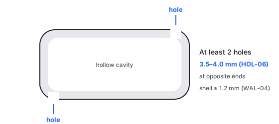
A hollow part needs at least two drain holes of 3.5–4.0 mm at opposite ends of the cavity (HOL-06), and a shell of at least 1.2 mm (WAL-04).
A hole that prints is not necessarily accurate. Orientation, depth, curing and finishing change its final size. Holes that need precision are drilled or reamed after printing (HOL-04).
| Rule | Name | Limit (mm, per side for gaps) |
|---|---|---|
HOL-01 | Minimum printable hole | Holes below 0.8 mm are ROUTE. min: 0.8. |
HOL-02 | Functional hole | Holes ≥1.0 mm AUTO_PASS; 0.8–<1.0 REVIEW. min: 1. Bands: AUTO_PASS ≥1.0; REVIEW 0.8–<1.0; ROUTE <0.8. |
HOL-03 | Open slot or gap | Minimum 0.5 mm in MATTE; GLOSSY/CLEAR use the GLOSSY static clearance (0.8 mm). MATTE: 0.5; GLOSSY: 0.8; CLEAR: 0.8. |
HOL-04 | Precision hole | Holes needing better than standard tolerance are post-drilled or reamed, or ROUTE. |
HOL-05 | Deep narrow hole | Depth/diameter above 5:1 is REVIEW (hard to wash and cure, tends to close up). |
HOL-06 | Drain holes | Hollow parts need at least two drain holes of 3.5–4.0 mm, placed at opposite extremes of the cavity. diameter: 3.5–4.0; count: ≥2. |
HOL-07 | Edge distance and bridges | Material between a hole or slot and the nearest outer edge must be ≥ max(2.0 mm, 1.5 × wall); CLEAR ≥ max(2.5 mm, 1.5 × wall). Thinner bridges are REVIEW down to 1.2 mm and ROUTE below. MATTE/GLOSSY: max(2.0, 1.5·t); CLEAR: max(2.5, 1.5·t). Bands: AUTO_PASS ≥ required; REVIEW 1.2 – < required; ROUTE <1.2. |
Use instead
- Wrong move: hollowing a model without drain holes. Why: uncured resin stays trapped inside. Right move: add at least two drain holes of 3.5–4.0 mm at opposite ends of the cavity (
HOL-06). The print panel's drain hole tool places 5 mm holes and asks for at least one per hollow pocket. That alone does not meetHOL-06: add a second hole at the opposite end of each cavity. - Wrong move: a slot close to the outer edge. Why: the thin bridge cracks. Right move: keep at least max(2.0, 1.5·t) mm of material to the edge, max(2.5, 1.5·t) on clear (
HOL-07).
Last checked: 2026-11-09. Womp version: Womp web app, November 2026.