Fits and clearances
How much gap to leave between parts that sit, slide, turn or link together, for each finish.Use this when: two printed parts touch, fit together or move against each other.
Don't use this for: a single part's size accuracy. That is tolerance, in Design rules.
All clearances are per side, surface to surface. A hole diameter is the shaft diameter plus 2 times the clearance (CLR-01).
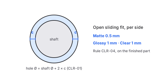
Clearance c is the gap on one side. The hole is the shaft diameter plus 2c. An open sliding fit needs 0.5 mm per side matte, 1 mm glossy (CLR-04).
Open fits
An open fit is one where only one pair of surfaces must clear, or the outer part can flex: a lid on a ledge, a part sliding along one rail, a shaft in a bore. Glossy values are larger because coating adds material and fuses small gaps.
| Rule | Name | Limit (mm, per side for gaps) |
|---|---|---|
CLR-01 | Clearance convention | All clearances are surface-to-surface gaps per side. Hole Ø = shaft Ø + 2 × clearance. |
CLR-02 | Loose static fit | Minimum gap per side for parts that sit together without moving. MATTE: 0.3; GLOSSY: 0.8; CLEAR: 0.8. |
CLR-03 | Removable lid or cover | Minimum gap per side for lids that are taken on and off by hand (open, non-enclosing fit). MATTE: 0.3–0.5; GLOSSY: 0.8–1.0; CLEAR: 0.8–1.0. |
CLR-04 | Open sliding fit | Minimum gap per side for a part sliding along one rail or face (not enclosed on all sides). MATTE: 0.5; GLOSSY: 1; CLEAR: 1. Bands: AUTO_PASS ≥ value; REVIEW MATTE 0.3–<0.5; GLOSSY 0.8–<1.0; ROUTE MATTE <0.3; GLOSSY <0.8. |
CLR-05 | Rotating shaft or hinge (round bore) | Minimum gap per side for a round shaft or hinge pin in a round bore. MATTE: 0.5; GLOSSY: 1; CLEAR: 1. |
CLR-06 | Interlocking chain links | Minimum gap per side between links. MATTE: 0.6; GLOSSY: 1.0–1.5 (prefer separate finishing); CLEAR: separate finishing only. |
CLR-07 | Print-in-place assembly | Assemblies printed already joined. MATTE: 0.6, REVIEW; GLOSSY: not recommended (ROUTE); CLEAR: not allowed (ROUTE). |
CLR-08 | Enclosed moving mechanism | A moving part fully enclosed so it cannot be washed, inspected or finished. MATTE: REVIEW; GLOSSY: ROUTE; CLEAR: ROUTE. |
CLR-09 | Precision alignment | Gaps below 0.3 mm per side for locating features. MATTE: REVIEW; GLOSSY: ROUTE; CLEAR: ROUTE. |
CLR-10 | Press and snap fits | Interference and snap fits are never auto-approved; resin- and geometry-specific testing is required. MATTE: ROUTE; GLOSSY: ROUTE; CLEAR: ROUTE. |
Closed fits
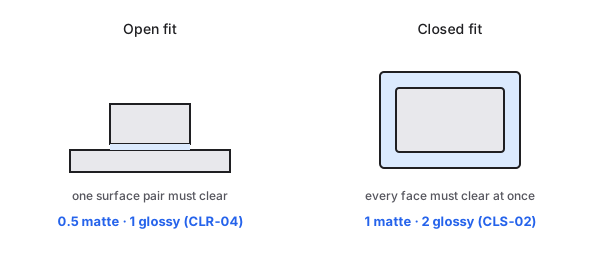
An open fit has one pair of surfaces to clear. A closed fit surrounds the part, so every face must clear at once: 1 mm per side matte, 2 mm glossy (CLS-02), against 0.5 and 1 mm for an open sliding fit (CLR-04). Wide flat walls bow and can need more.
A fit is closed when the mating surfaces form a complete loop around the inner part in cross-section: a box in a sleeve, a drawer in a case, a plug in a socket, a lid inside a rim (CLS-01). Every error on every face must clear at the same time, and the ring around the part cannot flex. A closed flat-walled fit needs at least 2 times the open sliding clearance: 1 mm matte, 2 mm glossy, 2 mm clear, per side (CLS-02).
| Rule | Name | Limit (mm, per side for gaps) |
|---|---|---|
CLS-01 | Detect closed perimeters | A fit is CLOSED when the mating surfaces form a complete loop around the inserted part in cross-section (box in sleeve, drawer in case, plug in socket, lid inside a rim). CLOSED fits use CLS rules instead of CLR-04. |
CLS-02 | Closed fits need at least 2× the open-fit clearance | Minimum gap per side for a closed flat-walled fit is at least 2 × the open sliding clearance; wide flat walls can need more. MATTE: 1; GLOSSY: 2; CLEAR: 2. Bands: AUTO_PASS ≥ required; REVIEW ≥ open-fit value and < required; ROUTE < open-fit value. |
CLS-05 | Long engagement | If the sliding engagement length exceeds 2 × the opening width, REVIEW for squareness and straightness. |
CLS-06 | Round bores | Round closed fits (shaft in hole, cap on round neck) use CLR-05: a round hoop has no flat span to bow. Polygonal and rectangular closed fits use CLS-02. |
CLS-07 | Design fixes for closed fits | Prefer contact on narrow rails or bumps rather than full faces; add 0.5–1.0 mm lead-in chamfers; add ribs to sleeve walls to cut bow; mask contact faces from coating. |
Round bores are the exception. A shaft in a round hole has no flat span to bow, so it uses the open rotating fit (CLS-06, CLR-05).
Use instead
- Wrong move: a box sliding in a sleeve with the open sliding gap. Why: the sleeve is a closed fit: walls bow toward each other and coating builds up on every face, so it jams. Right move: use the closed-fit gap (
CLS-02), slide on narrow rails, and add 0.5 to 1.0 mm lead-in chamfers (CLS-07). - Wrong move: a glossy chain or print-in-place hinge. Why: coating wicks into the gaps and fuses the links (
GLS-02,GLS-03). Right move: print it matte, or finish each link separately and assemble afterwards (CLR-06,CLR-07). - Wrong move: a press or snap fit. Why: they are never approved automatically; they need resin-specific testing (
CLR-10). Right move: a screw with a heat-set insert, or a magnet closure.
Last checked: 2026-11-09. Womp version: Womp web app, November 2026.